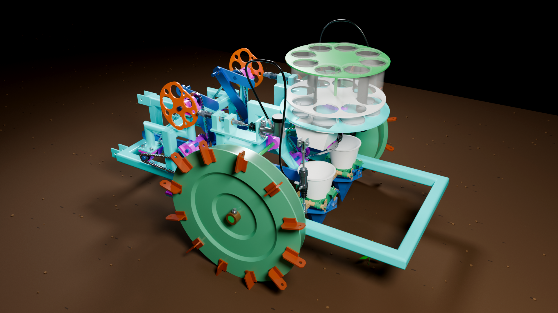
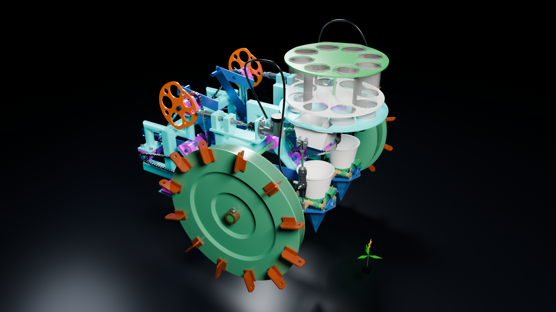
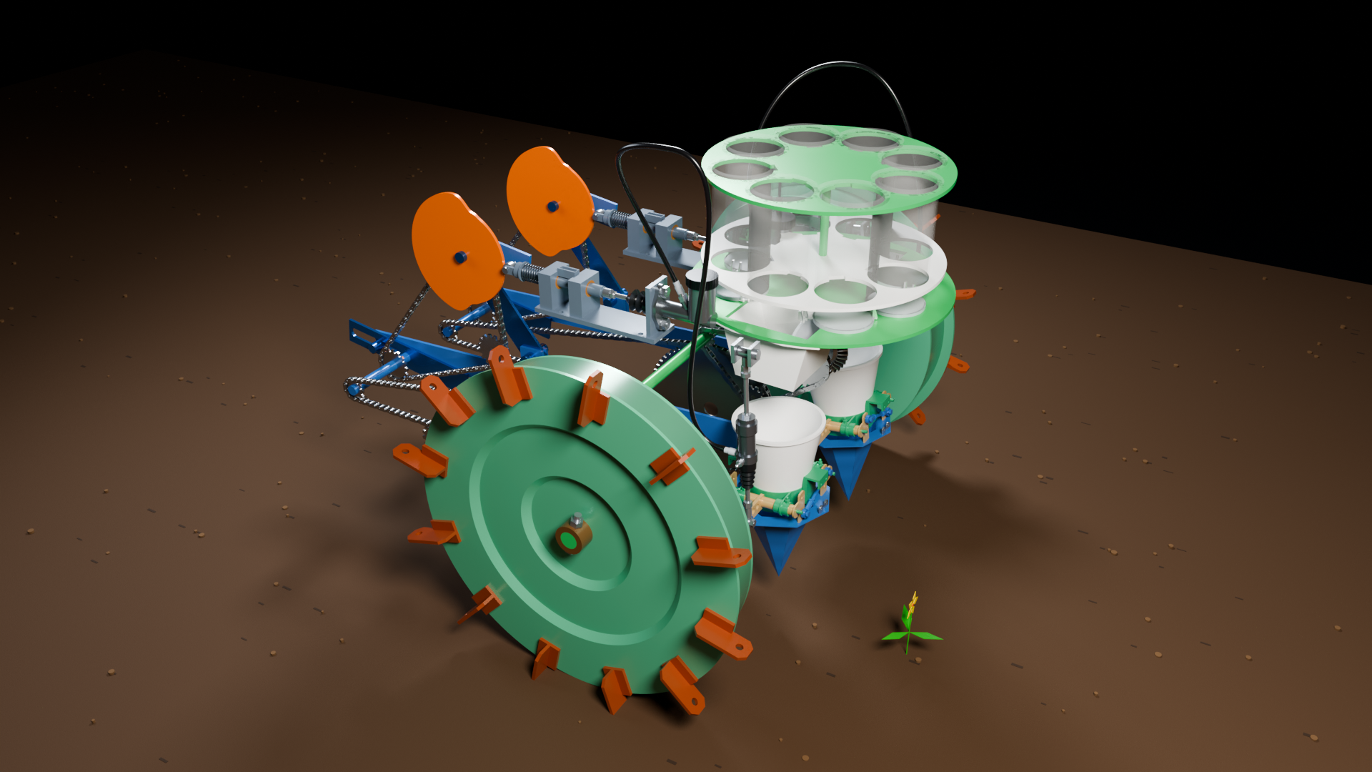
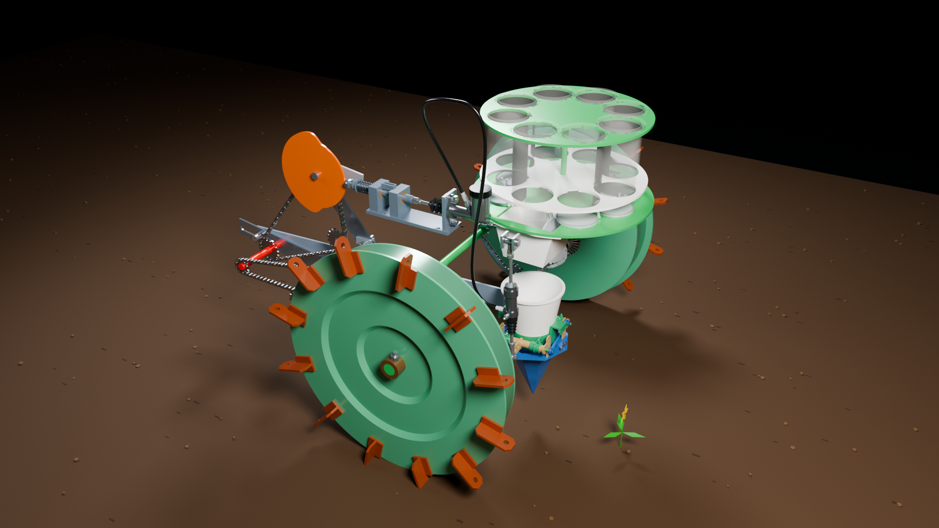
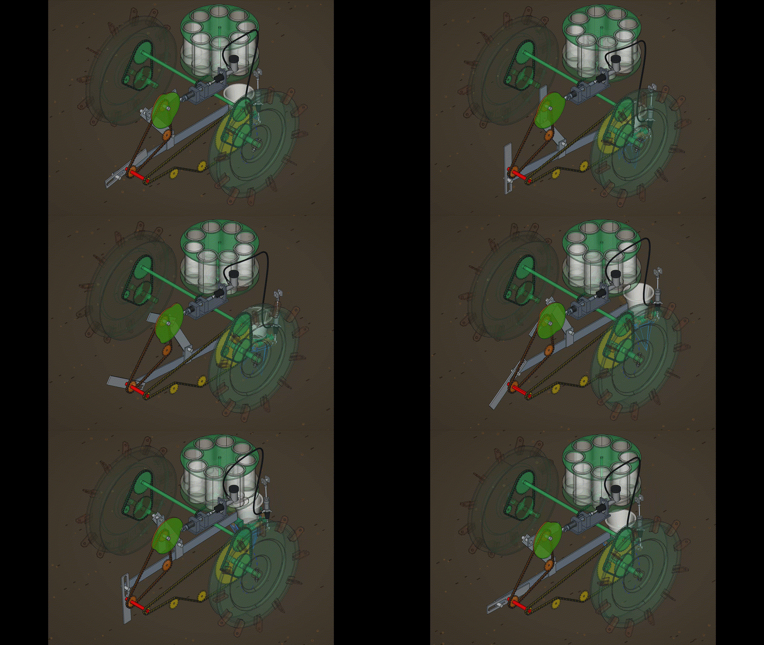
The plan is to create a simulated FreeCAD model so that all the geometry can be checked before going ahead into the fabrication stage. Parts will be made and arranged by means of Python macros created with the help of an LLM. So far so good.
Currently creating a motion simulated CAD drawing with an LLM
To make the experience fit your profile, pick a username and tell us what interests you.
We found and based on your interests.
The plan is to create a simulated FreeCAD model so that all the geometry can be checked before going ahead into the fabrication stage. Parts will be made and arranged by means of Python macros created with the help of an LLM. So far so good.
11_06_15.pngPortable Network Graphics (PNG) - 1.82 MB - 10/04/2026 at 10:09 |
|
|
10_17_44 PM.jpgJPEG Image - 172.96 kB - 10/03/2026 at 21:57 |
|
|
The big question is 'Is it worth actually going ahead and building the machine?' The CAD system is 100% accurate to real life and could be built just by following the info in the macro files on Github.

A few small details yet to add, including a chair for the operator to sit on.

The design is now about 95% complete, with a few small details yet to be added, such as the bearing inside the duck bill arms.
Normally there would be one carousel per transplanting station, but in this design one carousel feeds two parallel duck bill mechanisms. A human being operator sits on a chair near the carousel and feeds seedlings into the transparent tubes, making sure that the two tubes next in line to be dropped are always full. This gives the operator a bit of leeway to scratch their nose etc and not have to worry so much about missing the duck bill hopper. It's also a much safer way of interacting with the mechanism as the carousel is a relatively human friendly system compared to somebody trying to work with the duck bill hopper directly, which is inherently risky with relatively high chance of fingers / arms getting caught up in the fast moving, long travel mechanism.
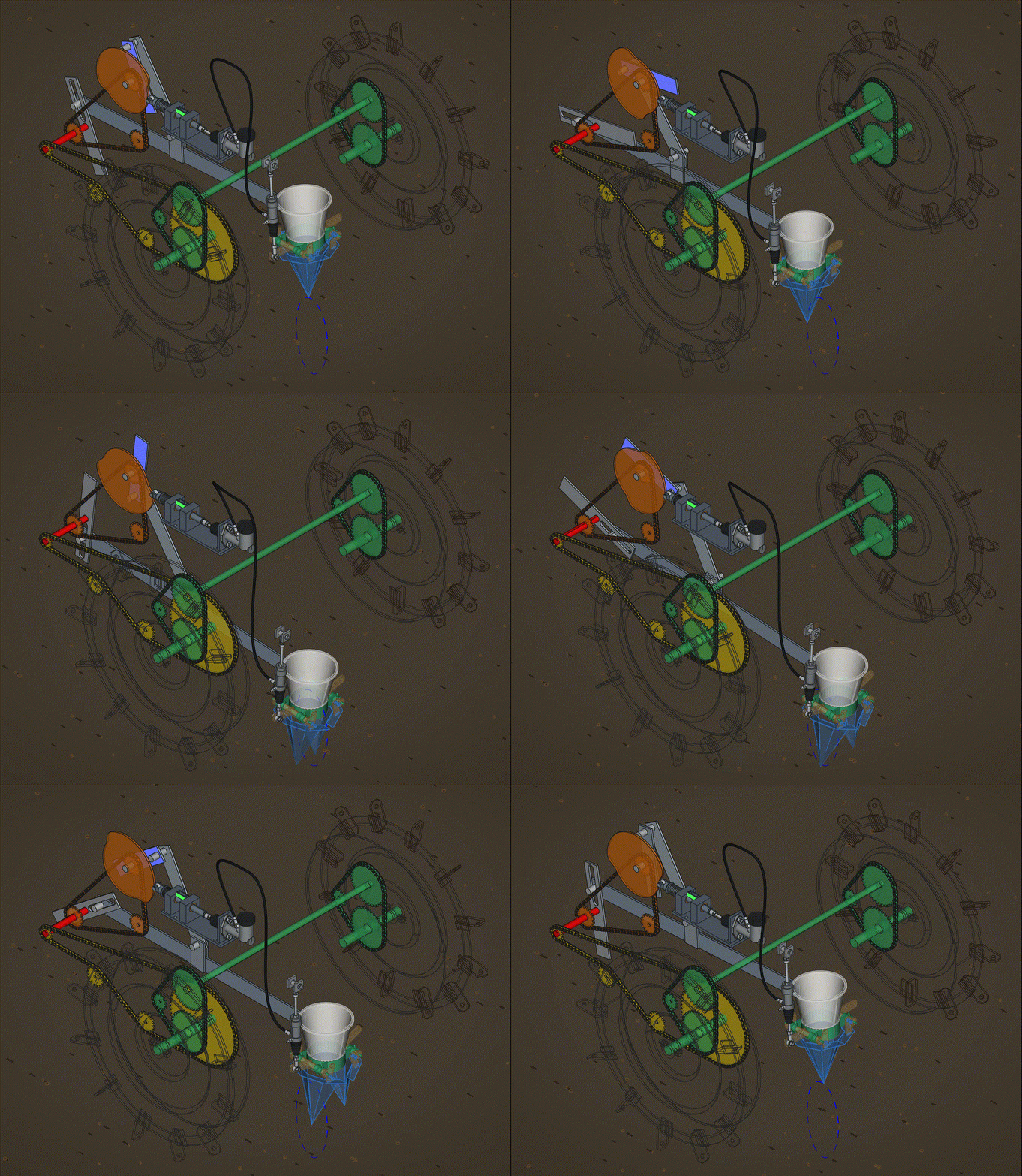
All the basic features of the mechanism are now complete. The machine now accepts a seedling into one of the carousel tubes and plants it accurately into the soil. The seedling produces a nice yellow flower.


Nearly 3 weeks into the project and the main components for the system are now in place, with a second duck bill ready to put in position. There's also some kind of flap disc needed under the carousel tubes to quickly release the seedlings into the duck bill hopper. The single carousel should be able to feed both duck bill systems simultaneously, which makes the design simpler.

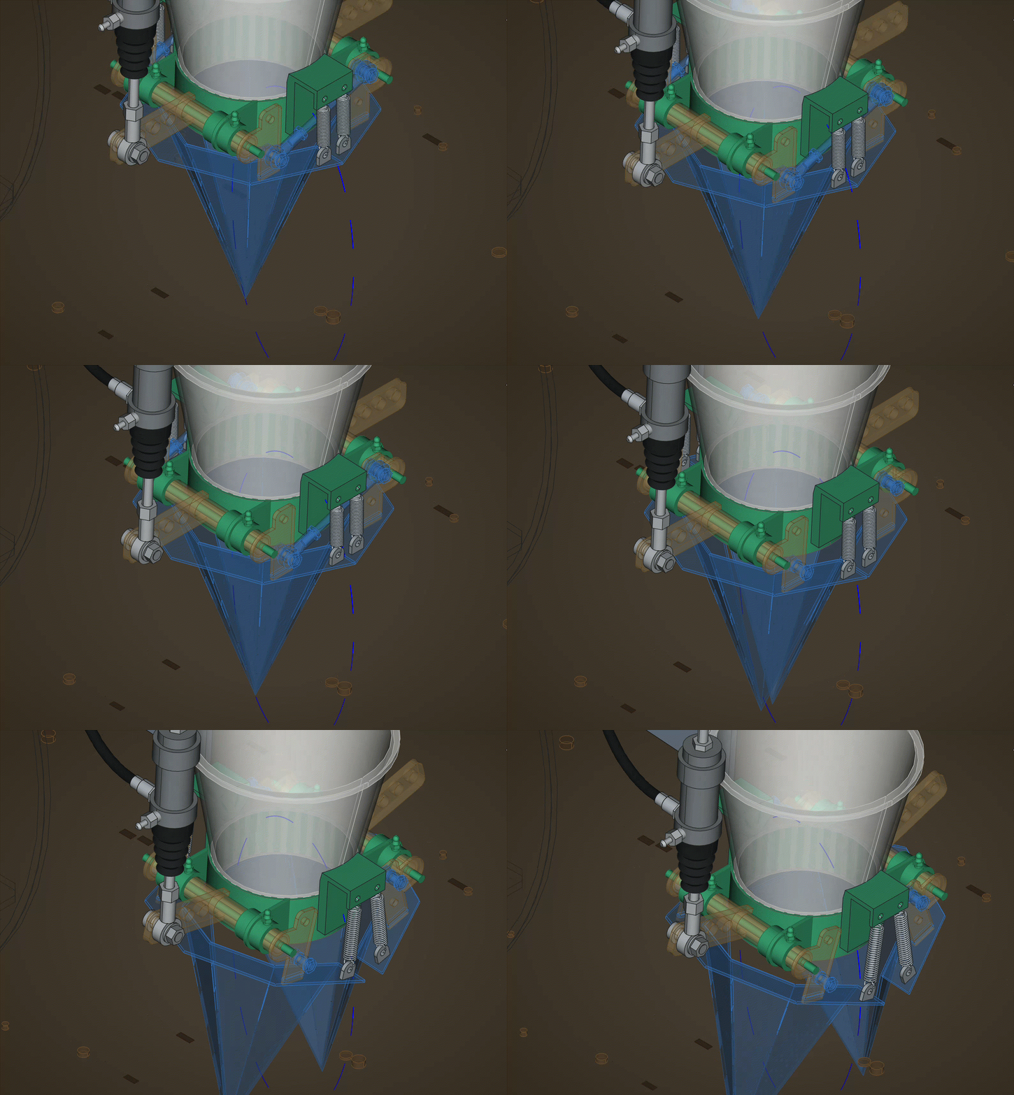
The duck bill is now opened by a hydraulic master cylinder and slave, similar to a vehicle clutch. Cables would have been a bit too tightly curved. The pushrod on the master cylinder wont tolerate sideways forces, so it needs an inline lateral interface for it to work of the cam disc. The duck bills need a couple of springs to bring them back to the closed position. The axle between the two drive wheels had to be cut out and raised up via chain and sprockets (coloured green) to allow the main duck bill arm to move without putting a horrible kink in it. The LLM managed to get a flexible pipe between the master and slave, which is pretty cool.

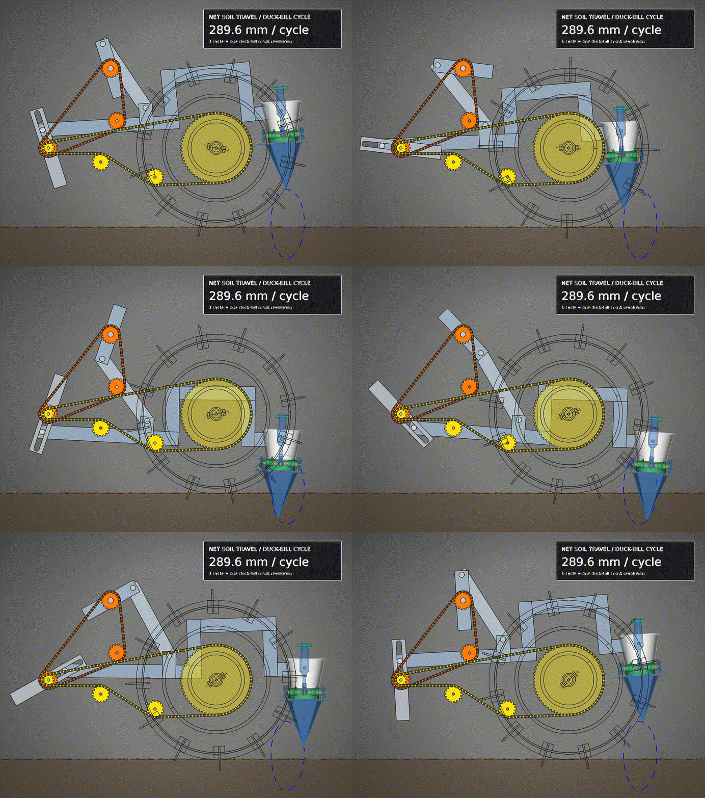
This mechanism was created and tuned with an LLM to primarily try and get the transplanting distance as close to 285mm as possible, it's currently 289.6 and make sure the duck bill, shown in blue, does not try and 'plough the earth' ie it's speed when it penetrates the soil is as close to zero relative to the soil in the left - right axis. Other than that, I was able to do further tuning to get the tip of the duck bill to trace an oval pathway shown in dashed blue and get that trace upright rather than slanting to one side.
The whole of this diagram is a Macro and is basically created through simple maths, though far too extensive for any normal human to put together manually. Any of the components shown can be exported as .dxf etc for laser cutting or other formats for 3D printing.
Compared to trying to create this mechanism by 'normal' CAD usage, I'd estimate using the LLM is now about 100 times faster than manually trying to tune the various arm lengths. For example, the LLM was able to move the various pivot points to get the duck bill tip pathway vertical and get the duck bill to match the soil speed in minutes rather than days.
The code is now about 10,000 lines long, mostly occupied by a 8,000 line base 64 encoded chunk representing another imported file. Without this import, the code would be about 3,000 lines long. See the Github repo for the latest files, just import the .FCMacro files as a macro into FreeCAD and you can see and the animation as above. If you want to edit the file - use an LLM !!
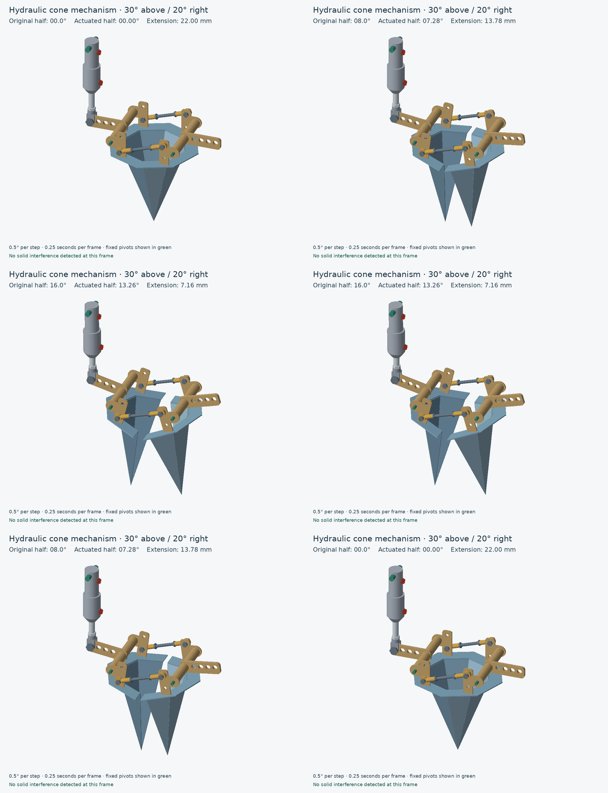
Part of a planting machine this assembly was modeled with the help of an LLM by using Python macros. The Macro is mechanically reproducible in real life and real, accurate dimensions can be extracted from it by importing it into FreeCAD. All this is only 850 lines of code !!!!!!!
The video below was produced from the macro by the LLM using Blender, which it installed on my PC in a Python environment. Took 12 hours to render 300 frames.
# Standalone comparison: complete closed and 20-degree mechanism in side view.
# Both poses share identical fixed pivot locations. All dimensions in mm.
import FreeCAD as App
import os
# Root profile trimmed for at least 1 mm band clearance through 25 degrees.
# 0 = outer hole; 1, 2, 3 move inward in 15 mm steps.
# Selecting another hole also relocates the rear mount to retain a vertical start.
CLEVIS_HOLE_INDEX = 0
def build_pose(requested_angle):
# FreeCAD macro: four-panel demi-cone; dimensions in mm.
# Standalone: uses only built-in FreeCAD/Part and Python modules.
# Dimensions refer to the theoretical sheet mid-surface.
import math
import os
import FreeCAD as App
import Part
SLANT_LENGTH = 180.0
RIM_CHORD = 50.0 # straight chord, NOT circular arc length
THICKNESS = 2.0
SLOT_WIDTH = 0.3 # nominal material removed before bending
TIP_KEEP = 30.0
RIM_KEEP = 20.0 # measured along each bend from its rim corner
SLOTS_PER_BEND = 3
PANELS = 4
FLANGE_WIDTH = 25.0 # horizontal distance normal to each straight rim edge
FLANGE_THICKNESS = 2.0
BRACKET_WIDTH = 20.0
BRACKET_LENGTH = 60.0 # extended 10 mm below the lowest hole
BRACKET_THICKNESS = 3.0
BRACKET_TOP_RADIUS = 5.0
BRACKET_HOLE_DIAMETER = 6.0
BRACKET_HOLE_FROM_TOP = 10.0
BRACKET_HOLE_SPACING = 15.0 # centre-to-centre downwards
BRACKET_HOLE_COUNT = 3
BRACKET_BELOW_FLANGE = 3.0
MOUNT_SLOT_LENGTH = 20.2 # along Y, perpendicular to open-back line
MOUNT_SLOT_WIDTH = 3.2 # along X
MOUNT_SLOT_X = 63.5 # mirrored centres at +/- X
MOUNT_SLOT_Y = 45.0 # from open-back line Y=0; estimated from screenshot
# Blank means save beside this macro (fallback: FreeCAD macro directory).
OUTPUT_DIR = ""
# Illustrative female rod ends, not a manufacturer's dimensioned part.
ROD_END_EYE_OD = 16.0
ROD_END_HOUSING_WIDTH = 6.0
ROD_END_BALL_WIDTH = 8.0
ROD_END_BALL_RADIUS = 5.0
ROD_END_EYE_TO_MOUTH = 25.0
ROD_END_SHANK_OD = 9.0
ROD_THREAD_DIAMETER = 6.0
ROD_THREAD_ENGAGEMENT = 10.0
ROD_END_SPACER = 1.0
PIVOT_OFFSET = 20.0 # each half outward: 40 mm additional separation
PIVOT_BOSS_RADIUS = 12.0 # 9 mm material beyond the 6 mm hole
PLAIN_BAR_LENGTH = 150.0
PLAIN_BAR_DIAMETER = 6.0
CYL_BASE_Y=-201.0 # corrected cylinder: retain 7 mm initial extension
CYL_BASE_X=63.5
CYL_BASE_HEIGHT_OFFSET=0.0 # rear pin level with clevis pin at zero degrees
CYL_STROKE=25.0 # retained operating envelope from previous model
CYL_REAR_PIN_DIAMETER=10.0 # catalogue rear bore is 10; clevis pin stays 6
RIGHT_TIE_SPACER=1.0 # standard tie-rod mounting restored; clevis uses other top hole
OPENING_ANGLE_DEG = requested_angle # original (+Y) half; driven half solved from fixed links
L = SLANT_LENGTH
C = RIM_CHORD
if PANELS != 4 or SLOTS_PER_BEND < 1:
raise ValueError("This macro requires four panels and at least one slot.")
if not (0 < C < 2*L and 0 < TIP_KEEP < L and 0 < RIM_KEEP < L-TIP_KEEP and THICKNESS > 0 and SLOT_WIDTH > 0):
raise ValueError("Invalid dimensions.")
alpha = 2 * math.asin(C / (2*L))
radius = C / (2*math.sin(math.pi/(2*PANELS)))
if radius >= L:
raise ValueError("Rim too large for the sloping length.")
height = math.sqrt(L*L - radius*radius)
# Equal slot lengths and equal internal bridges; both end margins stay intact.
pitch_piece = (L - TIP_KEEP - RIM_KEEP) / (2*SLOTS_PER_BEND - 1)
intervals = [(TIP_KEEP + 2*i*pitch_piece,
TIP_KEEP + (2*i+1)*pitch_piece) for i in range(SLOTS_PER_BEND)]
angles = [math.pi/2 + (i-PANELS/2)*alpha for i in range(PANELS+1)]
V = App.Vector
origin = V(0,0,0)
rim = [V(L*math.cos(a),...
Read more »

This device is called a Duck's Bill and moves down to the ground and releases the seedling enclosed within it at exactly the right moment. Some designs use a cable to do this and using a hydraulic actuator does seem like a bit of an over kill.
To see the mechanism, just copy the following code into a python file and upload into FreeCAD as a macro. If you want to remove the second, 20 degrees overlay, upload the file to LLM and ask it: "Remove the 20 degrees overlay".
# Standalone comparison: complete closed and 20-degree mechanism in side view.
# Both poses share identical fixed pivot locations. All dimensions in mm.
import FreeCAD as App
import os
# 0 = outer hole; 1, 2, 3 move inward in 15 mm steps.
# Selecting another hole also relocates the rear mount to retain a vertical start.
CLEVIS_HOLE_INDEX = 0
def build_pose(requested_angle):
# FreeCAD macro: four-panel demi-cone; dimensions in mm.
# Standalone: uses only built-in FreeCAD/Part and Python modules.
# Dimensions refer to the theoretical sheet mid-surface.
import math
import os
import FreeCAD as App
import Part
SLANT_LENGTH = 180.0
RIM_CHORD = 50.0 # straight chord, NOT circular arc length
THICKNESS = 2.0
SLOT_WIDTH = 0.3 # nominal material removed before bending
TIP_KEEP = 30.0
RIM_KEEP = 20.0 # measured along each bend from its rim corner
SLOTS_PER_BEND = 3
PANELS = 4
FLANGE_WIDTH = 25.0 # horizontal distance normal to each straight rim edge
FLANGE_THICKNESS = 2.0
BRACKET_WIDTH = 20.0
BRACKET_LENGTH = 60.0 # extended 10 mm below the lowest hole
BRACKET_THICKNESS = 3.0
BRACKET_TOP_RADIUS = 5.0
BRACKET_HOLE_DIAMETER = 6.0
BRACKET_HOLE_FROM_TOP = 10.0
BRACKET_HOLE_SPACING = 15.0 # centre-to-centre downwards
BRACKET_HOLE_COUNT = 3
BRACKET_BELOW_FLANGE = 3.0
MOUNT_SLOT_LENGTH = 20.2 # along Y, perpendicular to open-back line
MOUNT_SLOT_WIDTH = 3.2 # along X
MOUNT_SLOT_X = 63.5 # mirrored centres at +/- X
MOUNT_SLOT_Y = 45.0 # from open-back line Y=0; estimated from screenshot
# Blank means save beside this macro (fallback: FreeCAD macro directory).
OUTPUT_DIR = ""
# Illustrative female rod ends, not a manufacturer's dimensioned part.
ROD_END_EYE_OD = 16.0
ROD_END_HOUSING_WIDTH = 6.0
ROD_END_BALL_WIDTH = 8.0
ROD_END_BALL_RADIUS = 5.0
ROD_END_EYE_TO_MOUTH = 25.0
ROD_END_SHANK_OD = 9.0
ROD_THREAD_DIAMETER = 6.0
ROD_THREAD_ENGAGEMENT = 10.0
ROD_END_SPACER = 1.0
PIVOT_OFFSET = 20.0 # each half outward: 40 mm additional separation
PIVOT_BOSS_RADIUS = 12.0 # 9 mm material beyond the 6 mm hole
PLAIN_BAR_LENGTH = 150.0
PLAIN_BAR_DIAMETER = 6.0
CYL_BASE_Y=-201.0 # corrected cylinder: retain 7 mm initial extension
CYL_BASE_X=63.5
CYL_BASE_HEIGHT_OFFSET=0.0 # rear pin level with clevis pin at zero degrees
CYL_STROKE=25.0 # retained operating envelope from previous model
CYL_REAR_PIN_DIAMETER=10.0 # catalogue rear bore is 10; clevis pin stays 6
RIGHT_TIE_SPACER=1.0 # standard tie-rod mounting restored; clevis uses other top hole
OPENING_ANGLE_DEG = requested_angle # original (+Y) half; driven half solved from fixed links
L = SLANT_LENGTH
C = RIM_CHORD
if PANELS != 4 or SLOTS_PER_BEND < 1:
raise ValueError("This macro requires four panels and at least one slot.")
if not (0 < C < 2*L and 0 < TIP_KEEP < L and 0 < RIM_KEEP < L-TIP_KEEP and THICKNESS > 0 and SLOT_WIDTH > 0):
raise ValueError("Invalid dimensions.")
alpha = 2 * math.asin(C / (2*L))
radius = C / (2*math.sin(math.pi/(2*PANELS)))
if radius >= L:
raise ValueError("Rim too large for the sloping length.")
height = math.sqrt(L*L - radius*radius)
# Equal slot lengths and equal internal bridges; both end margins stay intact.
pitch_piece = (L - TIP_KEEP - RIM_KEEP) / (2*SLOTS_PER_BEND - 1)
intervals = [(TIP_KEEP + 2*i*pitch_piece,
TIP_KEEP + (2*i+1)*pitch_piece) for i in range(SLOTS_PER_BEND)]
angles = [math.pi/2 + (i-PANELS/2)*alpha for i in range(PANELS+1)]
V = App.Vector
origin = V(0,0,0)
rim = [V(L*math.cos(a), L*math.sin(a), 0) for a in angles]
def face...
Read more »
Create an account to leave a comment. Already have an account? Log In.
Become a member to follow this project and never miss any updates
About Us Contact Hackaday.io Give Feedback Terms of Use Privacy Policy Hackaday API Do not sell or share my personal information
Jesal Mehta
charliex
Steel_9
Brandon Piner