

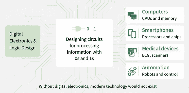
Digital Electronics is a branch of electronics that deals with digital signals (0 and 1) instead of continuous analog signals.
- It forms the foundation of modern digital systems such as computers, microprocessors, embedded systems, and communication devices.
- Digital Electronics uses logic gates, Boolean algebra, and sequential circuits to process and store digital information.
- Examples: Logic Gates, Boolean Algebra, Flip-Flops, Counters, Registers, Multiplexers, Microprocessors, and Memory Circuits.
1. What is Boolean Algebra?
Boolean Algebra is a mathematical system used to represent and simplify logical expressions in digital electronics. It works with only two binary values, 0 (False) and 1 (True), and forms the basis for designing and analyzing digital circuits using logic gates.
Example:
- AND (·)
- OR (+)
- NOT (')
2. What are the Properties of Boolean Algebra?
Some basic switching properties of Boolean algebra are:
- Associative law: A + (B + C) = (A + B) + C; A.(B.C) = (A.B).C
- Absorption law: A. (A + B) = A; A + AB = A
- Complement law: A + A’ = 1 ; A.A’ = 0
- Commutative law: A + B = B + A; A.B = B.A
- De Morgan Law: (A.B)’ = A’ + B’ ; (A + B)’ = A’.B’
- Distributive law: A. (B + C) = (A.B) + (A.C)
- Double negation law: ((A)’)’ = A
- Identity law: A.1 = A; A + 0 = A
- Idempotent law: A + A = A; A.A = A
3. Explain De Morgan's Theorem.
De Morgan's Theorem is one of the fundamental laws of Boolean Algebra. It is used to simplify Boolean expressions and implement logic circuits more efficiently.
The theorem consists of two laws:
- The complement of the product of two variables is equal to the sum of their complements.
(AB)' = A' + B' - The complement of the sum of two variables is equal to the product of their complements.
(A + B)' = A'B'
4. What is Duality Theorem?
The Duality Theorem states that every valid Boolean expression has a corresponding dual expression, which can be obtained by:
- Replacing every OR (+) operator with AND (·), and vice versa.
- Replacing every 0 with 1, and every 1 with 0.
- Keeping the Boolean variables (A, B, C, ...) unchanged.
Example:
- Original Expression: A(B + C)
- Dual Expression: A + (B.C)
Since, A + (B.C) = (A + B)(A + C) by the distributive law, both expressions are equivalent.
5. What is a Logic Gate?
A logic gate is a basic digital circuit that performs logical operations on one or more binary inputs to produce a single binary output. It is the fundamental building block of digital circuits and operates using Boolean Algebra.
The output of a logic gate depends on the combination of its input values. Logic gates are used to design digital systems such as computers, microprocessors, calculators, and communication devices.
6. What are the types of Logic Gates?
There are three basic logic gates, two universal gates, and a few other combinational logic gates in digital electronics.
Basic Gates
- AND gate: Produces 1 only when all inputs are 1.
- OR gate: Produces 1 if at least one input is 1.
- NOT gate: Inverts the input (0 becomes 1, and 1 becomes 0).
Universal Gates
Other Gates:
- XOR gate: Produces 1 when the inputs are different.
- XNOR gate: Produces 1 when the inputs are the same.
7. What is Gray code?
Gray Code, also known as Reflected Binary Code, is a binary numbering system in which two consecutive numbers differ by only one bit. This reduces errors during the transition from one binary number to another, making Gray Code widely used in digital systems such as rotary encoders, position sensors, and analog-to-digital converters (ADCs).
8. How many types of Number Systems are there?
A number system is a method of representing numbers using a specific set of digits and a base (radix). In digital electronics, the four commonly used number systems are:
- Binary Number System: Uses only 0 and 1.
- Octal Number System: Uses digits 0 to 7.
- Decimal Number System: Uses digits 0 to 9.
- Hexadecimal Number System: Uses digits 0 to 9 and letters A to F.
9. What is Encoder and Decoder?
An Encoder and Decoder are combinational logic circuits.
- Encoder: An encoder converts 2ⁿ input lines into n output lines by generating a binary code corresponding to the active input.
- Decoder: A decoder performs the reverse operation of an encoder. It converts n input lines into 2ⁿ output lines by activating the corresponding output line based on the input code.
Example: An 8-to-3 encoder converts 8 input lines into a 3-bit binary output, while a 3-to-8 decoder converts a 3-bit binary input into one of 8 output lines.
10. Explain the Difference Between Sequential and Combinational Circuits.
Combinational Circuit
- The output depends only on the present input values.
- It does not store any previous data, so no memory element required.
- It is simpler to design and implement.
- It works faster because there is no memory operation.
- It is made only using logic gates.
- Examples are adder, subtractor, multiplexer, encoder, and decoder.
Sequential Circuit
- The output depends on the present inputs as well as the previous state.
- It stores information, so memory elements are required.
- It is more complex to design and implement.
- It is comparatively slower because memory and clock operations are involved.
- It is built using logic gates along with flip-flops or latches.
- Examples are counter, register, shift register, and flip-flop circuits.
11. What are the Flip-Flops?
A Flip-Flop is a basic memory element in digital electronics. It is a sequential circuit that stores one bit of binary data and has two stable states: Logic 0 (LOW) and Logic 1 (HIGH). A flip-flop is also known as a Bistable Multivibrator.
Flip-flops are widely used in memory devices, registers, counters, shift registers, frequency division, and data transfer.
12. What is the Difference Between Latch And Flip-flop?
Flip-Flop
- A flip-flop is a memory element that can store one bit, either 0 or 1.
- It is an edge-triggered device.
- The output changes only when a clock edge occurs.
- It works under the control of a clock signal.
- It is more reliable for synchronous digital circuits.
Latch
- A latch is also a memory element that can store one bit, either 0 or 1.
- It is a level-triggered device.
- The output changes as long as the enable signal is active.
- It is controlled by an enable or control signal, not by a clock edge.
- It is simpler and faster, but unwanted changes may occur because it continuously responds to the input.
13. Explain the types of Flip Flop.
There are four main types of Flip-Flops, each designed for a specific operation:
- SR (Set-Reset) Flip-Flop: Stores or resets a bit using Set (S) and Reset (R) inputs.
- JK Flip-Flop: An improved version of the SR Flip-Flop that eliminates the invalid state and can toggle its output.
- D (Data/Delay) Flip-Flop: Stores the value present at the D input on the active clock edge and is widely used in registers and memory circuits.
- T (Toggle) Flip-Flop: Toggles its output between 0 and 1 on every clock pulse when the input is HIGH. It is commonly used in counters.
14. Difference between JK and SR Flip Flop?
JK Flip-Flop
- JK flip-flop is an improved version of the SR flip-flop.
- It does not have an invalid state.
- When J = 1 and K = 1, the output toggles.
- It can perform Set, Reset, Hold, and Toggle operations.
- The circuit is slightly more complex.
- It is used in counters, registers, and frequency division circuits.
SR Flip-Flop
- SR flip-flop is the basic flip-flop with Set (S) and Reset (R) inputs.
- It has an invalid condition when S = 1 and R = 1.
- It is used less often because of this invalid state.
- It can perform Set, Reset, and Hold operations only.
- The circuit is simpler.
- It is mainly used for basic memory storage and control circuits.
15. What is Master-Slave JK Flip Flop?
A Master-Slave JK Flip-Flop is a sequential circuit made by connecting two JK flip-flops in series. The first flip-flop acts as the Master, while the second acts as the Slave.
The Master stores the input data during one half of the clock cycle, and the Slave updates the output during the other half using the inverted clock signal. This arrangement ensures that the output changes only once per clock cycle, eliminating the race-around condition.
Applications: Used in counters, registers, and other synchronous digital circuits where reliable data storage and transfer are required.
16. What is Half-Adder?
A Half Adder is a combinational logic circuit used to add two single-bit binary numbers. It produces two outputs:
- Sum (S) - Represents the addition result.
- Carry (C) - Represents the carry generated during addition.
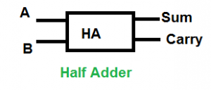
A Half Adder has two inputs (A and B) and does not have a carry input, making it suitable for adding only two single-bit numbers.
17. What is a Full Adder?
A Full Adder is a combinational logic circuit used to add three single-bit binary inputs: A, B, and Carry-In (Cin). It produces two outputs:
- Sum (S) - Represents the result of the addition.
- Carry-Out (Cout) - Represents the carry generated after addition.
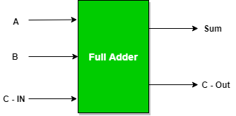
Full Adder can add a carry input, making it suitable for connecting multiple adders to perform multi-bit binary addition.
18. What is a Multiplexer?
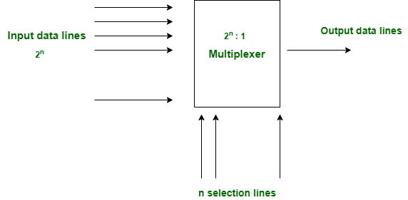
A Multiplexer (MUX) is a combinational logic circuit that selects one of many input signals and forwards it to a single output based on the select (control) lines.
For 2ⁿ input lines, a multiplexer requires n select lines.
Applications:
- Used in time-division multiplexing (TDM) systems.
- Used as a data selector.
- Used in data acquisition systems.
- Used for parallel-to-serial data conversion.
19. What is a Demultiplexer?
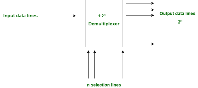
A Demultiplexer (DEMUX) is a combinational logic circuit that takes one input and distributes it to one of many output lines based on the select (control) lines.
For n select lines, a demultiplexer provides 2ⁿ output lines.
Applications:
- Used as a data distributor.
- Used for serial-to-parallel data conversion.
- Used in communication and data transmission systems.
20. What is meant by K-Map or Karnaugh Map?
A Karnaugh Map (K-Map) is a graphical method used to simplify Boolean expressions. It helps minimize logic circuits by reducing the number of logic gates required, making the circuit simpler, faster, and more efficient.
K-Maps are mainly used for 3-variable and 4-variable Boolean expressions. They simplify expressions without using Boolean algebra laws and can be used to obtain both Sum of Products (SOP) and Product of Sums (POS) forms.
21. Difference between SOP and POS?
SOP (Sum of Products)
- In SOP form, a Boolean expression is written as OR of AND terms.
- It is made using minterms.
- We consider the input combinations where the output is 1.
- It is written as Σm.
- If a variable value is 1, it is written in normal form. If the value is 0, it is written in complemented form.
POS (Product of Sums)
- In POS form, a Boolean expression is written as AND of OR terms.
- It is made using maxterms.
- We consider the input combinations where the output is 0.
- It is written as ΠM.
- If a variable value is 1, it is written in complemented form. If the value is 0, it is written in normal form.
22. Explain the Consensus Theorem.
Answer:
The Consensus Theorem is a Boolean algebra theorem used to simplify Boolean expressions by eliminating redundant terms, resulting in simpler and more efficient digital circuits.
The theorem is expressed as:
AB + A'C + BC = AB + A'C
Here, BC is called the consensus term. Since it does not affect the final output, it can be removed without changing the result.
Example:
AB + A'C + BC = AB + A'C
After applying the Consensus Theorem, the simplified expression is: AB + A'C
23. Explain the Quine-McCluskey Method.
The Quine-McCluskey Method, also known as the Tabulation Method, is a systematic technique used to simplify Boolean expressions. It minimizes Boolean functions by identifying and combining prime implicants to obtain the simplest expression.
This method is especially useful for simplifying Boolean expressions with more than four variables, where Karnaugh Maps (K-Maps) become difficult to use.
24. Define Pair, Quad, and Octet.
Answer:
- Pair: A group of two adjacent cells in a K-Map. It eliminates one variable during Boolean expression simplification.
- Quad: A group of four adjacent cells in a K-Map. It eliminates two variables during simplification.
- Octet: A group of eight adjacent cells in a K-Map. It eliminates three variables during simplification.
25. Discuss Various Implicants in K-Map
An Implicant is a group of one or more adjacent minterms (in SOP) or maxterms (in POS) used to simplify a Boolean expression in a K-Map.
The different types of implicants are:
- Prime Implicant (PI): The largest possible group of adjacent cells that cannot be combined further in a K-Map.
- Essential Prime Implicant (EPI): A prime implicant that covers at least one minterm not covered by any other prime implicant. It must be included in the final simplified expression.
- Redundant Prime Implicant (RPI): A prime implicant whose minterms are already covered by essential prime implicants. It is not required in the final expression.
- Selective Prime Implicant (SPI): A prime implicant that is neither essential nor redundant. It may or may not be included in the final solution, depending on the simplification.
26. What are Standard and Canonical Forms?
Standard Form: A Boolean expression in which every term contains all the variables, either in true or complemented form. It can be represented as Sum of Products (SOP) or Product of Sums (POS).
Canonical Form: A special type of standard form in which every term is a minterm (for SOP) or a maxterm (for POS).
- Canonical SOP = Sum of Minterms (Output = 1)
- Canonical POS = Product of Maxterms (Output = 0)
27. What is Functional Completeness?
A set of Boolean operations is said to be functionally complete (or universal) if every Boolean function can be implemented using only those operations.
Examples of functionally complete sets are:
- {AND, OR, NOT}
- {AND, NOT}
- {OR, NOT}
28. Write Down the Characteristics of Digital ICs.
The main characteristics of Digital ICs are:
- Propagation Delay: The time taken for the output to respond after the input changes.
- Power Dissipation: The amount of power consumed by the IC during operation.
- Fan-In: The maximum number of inputs a logic gate can accept.
- Fan-Out: The maximum number of logic gate inputs that can be driven by the output of a gate without affecting its performance.
- Noise Margin: The maximum amount of unwanted noise a circuit can tolerate without changing the correct output.
29. Define Rise Time, Fall Time, Hold Time, and Setup Time.
- Rise Time (tr): The time required for a signal to change from 10% to 90% of its final voltage level.
- Fall Time (tf): The time required for a signal to change from 90% to 10% of its voltage level.
- Hold Time (thold): The minimum time for which the input data must remain stable after the active clock edge to ensure correct operation of the flip-flop.
- Setup Time (tsetup): The minimum time for which the input data must remain stable before the active clock edge to ensure correct operation of the flip-flop.
30. What is a Race Condition in Digital Circuits?
A Race Condition occurs when two or more signals change simultaneously, causing the output to become unpredictable due to different propagation delays in the circuit.
Race conditions are commonly observed in sequential circuits, especially in JK Flip-Flops, where they can lead to incorrect or unstable outputs.
31. What is a Hazard?
A Hazard is a temporary and unwanted change (glitch) in the output of a digital circuit caused by different propagation delays in the logic paths. It occurs when input signals change, but the output does not update simultaneously due to unequal delays.
The three main types of hazards are:
- Static Hazard
- Dynamic Hazard
- Functional Hazard
32. Difference Between Static and Dynamic Hazards
Static Hazard
- The output should remain the same, either 0 or 1, but it changes for a very short time because of delay in the circuit.
- It happens when different logic paths have different propagation delays.
- It is easier to detect and remove.
- It can be removed by adding extra logic terms.
Dynamic Hazard
- The output should change only once, but it changes multiple times before becoming stable.
- It occurs in multilevel logic circuits due to unequal propagation delays.
- It is harder to detect and remove.
- It can be reduced by removing static hazards and simplifying the circuit.
33. What is a Mealy Machine?
A Mealy Machine is a finite state machine (FSM) in which the output depends on both the current state and the current input. As a result, the output can change immediately when the input changes.
34. What is a Moore Machine?
A Moore Machine is a finite state machine (FSM) in which the output depends only on the current state. The output changes only when the state changes, making it more stable than a Mealy machine.
35. What is a Counter?
A Counter is a sequential logic circuit used to count the number of clock pulses or events. It is built using flip-flops and changes its output state with each clock pulse according to a predefined sequence.
Counters are widely used in digital clocks, timers, frequency counters, and digital control systems.
Counters are broadly classified into two types:
- Asynchronous (Ripple) Counter
- Synchronous Counter
36. Difference Between Synchronous and Asynchronous Counters
Synchronous Counter
- In a synchronous counter, all flip-flops receive the clock pulse at the same time.
- It works faster.
- It is also called a parallel counter.
- The propagation delay is low.
- Examples are ring counter and Johnson counter.
Asynchronous Counter
- In an asynchronous counter, the output of one flip-flop is used to trigger the next flip-flop.
- It works slower because of propagation delay.
- It is also called a ripple counter.
- The propagation delay is high.
- Examples are ripple up counter and ripple down counter.
37. What is a Johnson Counter?
A Johnson Counter, also known as a Twisted Ring Counter or Creeping Counter, is a synchronous shift register counter in which the complemented output of the last flip-flop is fed back to the input of the first flip-flop.
An n-bit Johnson Counter requires n flip-flops and produces 2n unique states, making it useful for sequence generation and timing applications.
Applications:
- Sequence generators
- Timing circuits
- Frequency division
- Digital counters
38. Up to how many states can a Ripple Counter count?
A Ripple Counter (Asynchronous Counter) with n flip-flops can count up to 2ⁿ states before repeating its counting sequence. Therefore, it is also called a MOD-2ⁿ Counter.
Features:
- It is an asynchronous counter.
- All flip-flops operate in toggle mode.
- Only the first flip-flop receives the external clock signal.
- The remaining flip-flops are triggered by the output of the previous flip-flop.
- It has a ripple effect, resulting in higher propagation delay.
39. What are Shift Registers?
A Shift Register is a sequential logic circuit made up of flip-flops that is used to store and shift binary data. The stored data is shifted left or right by one bit with each clock pulse.
An n-bit shift register is constructed using n flip-flops.
Types of Shift Registers:
- SISO (Serial In Serial Out) - Data enters and exits serially.
- SIPO (Serial In Parallel Out) - Data enters serially and exits in parallel.
- PISO (Parallel In Serial Out) - Data enters in parallel and exits serially.
- PIPO (Parallel In Parallel Out) - Data enters and exits in parallel.
40. Explain Ring Counter
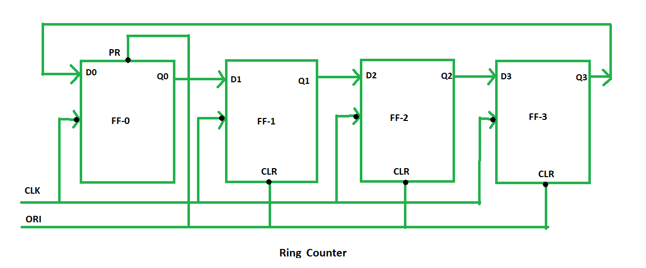
A Ring Counter is a synchronous shift register counter in which the output of the last flip-flop is connected to the input of the first flip-flop. A single '1' (or '0') circulates through the flip-flops with each clock pulse.
The number of states in a ring counter is equal to the number of flip-flops (n).
For example, a 4-bit Ring Counter requires 4 flip-flops and has 4 unique states.
41. Difference between PLA and PAL?
PLA (Programmable Logic Array)
- In PLA, both the AND gate section and OR gate section can be programmed.
- It is more flexible and can implement many logic functions.
- Because of this flexibility, it works a little slower.
- Designing PLA is comparatively difficult.
- Its cost is higher.
PAL (Programmable Array Logic)
- In PAL, only the AND gate section is programmable, while the OR gate section is fixed.
- It is less flexible than PLA.
- PAL works faster than PLA.
- It is easier to design.
- Its cost is lower.
42. Difference Between Digital And Analog Systems?
Analog System
- Uses continuous signals to represent information.
- Information is represented using continuous values.
- Uses sine waves.
- More affected by noise and signal distortion.
- Lower accuracy and more difficult to store and process.
Digital System
- Uses discrete (binary) signals to represent information.
- Information is represented using 0s and 1s.
- Uses square waves.
- Less affected by noise and provides better reliability.
- Higher accuracy and easier to store, process, and transmit.
43. Difference between Baseband and Broadband Transmission?
Baseband Transmission
- Uses digital signals for data transmission.
- A single communication channel is used.
- Suitable for short-distance communication.
- The entire bandwidth is used by a single signal.
- Simpler and less expensive.
Broadband Transmission
- Uses analog signals or modulated carriers for data transmission.
- Multiple communication channels can be used simultaneously.
- Suitable for long-distance communication.
- The bandwidth is divided into multiple frequency channels.
- More complex and expensive.
