

A transistor-based XNOR gate implements the Exclusive-NOR (XNOR) logic function using multiple NPN transistors that act as electronic switches.
- Multiple NPN transistors are connected to perform the XNOR operation.
- The output becomes HIGH (1) only when both input signals are the same.
- The output becomes LOW (0) when the two input signals are different.
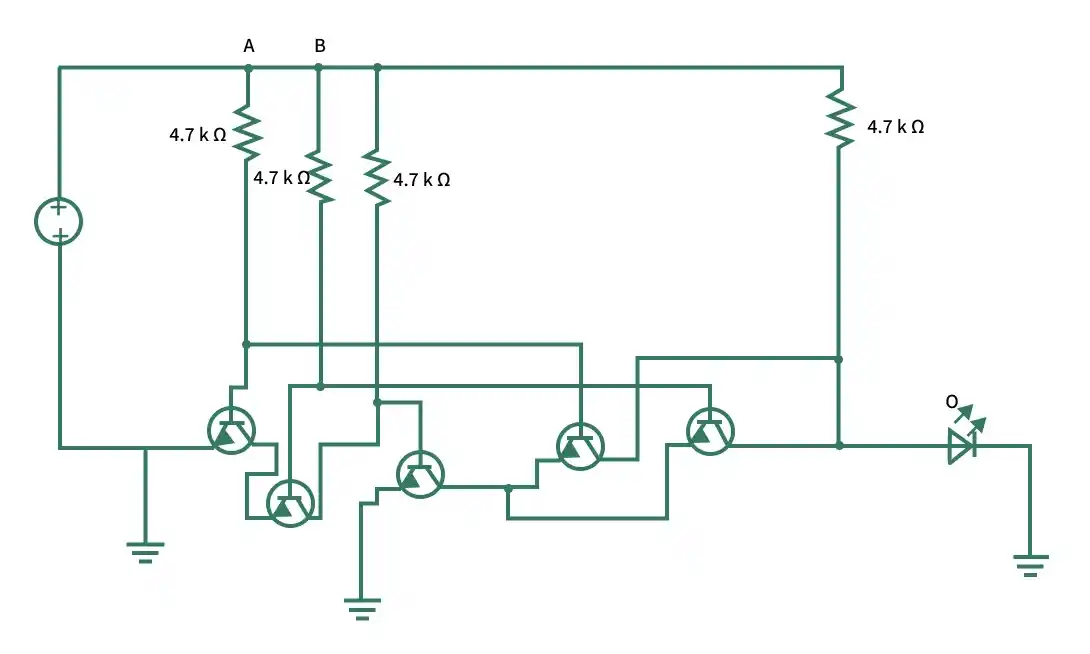
Circuit Components
- Five NPN Transistors: Act as electronic switches to implement the XNOR operation.
- Input Terminals (A and B): Apply the binary input signals to the transistor bases.
- Resistors (4.7 kΩ): Limit the base current, provide proper biasing, and protect the transistors.
- LED: Indicates the output state of the XNOR gate.
- Power Supply (VCC): Provides the required DC operating voltage for the circuit.
- Output: Produces the XNOR gate output according to the input conditions.
Working Principle
The operation of the transistor-based XNOR gate depends on the switching states of the transistors.
- A = 0, B = 0: The transistor network produces a HIGH (1) output, causing the LED to glow.
- A = 0, B = 1: The transistor switching path changes, producing a LOW (0) output. The LED remains OFF.
- A = 1, B = 0: The transistor network again produces a LOW (0) output, so the LED remains OFF.
- A = 1, B = 1: The transistors switch to produce a HIGH (1) output, causing the LED to glow.
This transistor arrangement ensures that the output becomes HIGH only when both input signals are identical, demonstrating the behavior of an XNOR gate.
