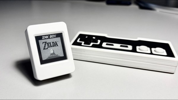
Tiny E-Paper Display Delivers 30 FPS Of Game Boy Fun

Slow refresh, ghosting and low-contrast — wait, are we talking about passive matrix LCDs, or e-paper displays? That might be why e-paper Game Boy emulators are a thing: the limitations of the black-on-grey e-paper screens remind us of the grey-on-green LCDs Nintendo used in the 80s. In this case [Bo Made It] made it out of a Waveshare ESP32-S3-ePaper-1.54, and got 30 FPS from it. 

Now, regular readers might be thinking, “So, we’ve seen the 60 FPS e-paper monitor, how is this special?” It’s a fair question. The answer is that [Bo] is doing this on a randomly chosen dev board with a built in wavetable e-paper controller, rather than the bare inputs that allowed the [Wenting Zhang]’s project to work. On the other hand, [Bo] does credit [Wenting], particularly his e-ink PaperBoy project, with directly inspiring both the project and his implementation.

Again, the big difference is going through the blob of the controller, but it turns out you can still address individual pixels through it. [Bo] gave each pixel a ‘budget’ for up to 8 pulses it depending on how much it needs to change, speeding things up immensely. Our favorite part is how he achieves the Game Boy’s 4-bit greyscale by, in effect, deliberately ghosting the display. Pixels aren’t driven long enough to fully flip them if they’re going only one shade lighter or darker. This complicated matters, since going from black to ‘white’ now takes longer than ‘white’ to the next darker grey, and the exact timing needs to be worked out for each color transition. Getting that timing right took a lot of calibration, and we like how he used video to help automate the process.

That process is still ongoing, so there’s no GitHub link yet. [Bo] will open source everything when it’s ready, and we look forward to it. We also look forward to the PDA-like device he’s going to be using this display driver for. If this all sounds similar to a recent 20 FPS e-paper hack, that’s because it’s the same underlying technology.

Continue reading “Tiny E-Paper Display Delivers 30 FPS Of Game Boy Fun” →
Inside A Mystery 1980s Filter IC Featuring Switched Capacitors

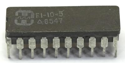
Recently [Ken Shirriff] got handed a mystery IC by [CuriousMarc] who had found said IC in a box of various old chips. Labelled only with a date code of the 47th week of 1985 and a mysterious F1-10-5 alongside a logo that didn’t lead to any hits in the typical IC databases, it was up to [Ken] to figure out what lurks inside this CDIP chip.

As it turns out, it’s actually a pretty interesting IC with an easy to identify die once the ceramic package had been cracked open with a surgical hammer-and-chisel strike.

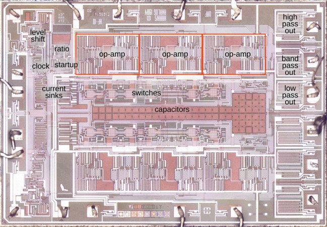
With the die under a microscope it was identified as a Harris HF10, itself a variant of the National Semiconductor MF10. This is a dual switched capacitor filter, with the modern version being e.g. the TI MF10-N in both PDIP and SOIC, but sadly no CDIP any more. Availability seems scarce, so the MF10 may not be long for this world.

These filter ICs can tune their capacitors to act as a low-, band- or high-pass filter. How this works is explained by [Ken], with switched capacitors replacing the resistors of a typical filter circuit. The main reasons for doing this over just using a resistor include how large resistors can get compared to the relatively small capacitor, not to mention their fixed value versus the adjustable resistance from the switchable capacitor.

The remainder of the circuit is mostly there to enable the switching and overall operation, providing a fascinating glimpse at a chip that would have been incredibly useful in the 1980s, including in synthesizers where this adjustable filter feature was most convenient.

Poking At The Radxa Dragon Q8B Raspberry Pi 5 Killer

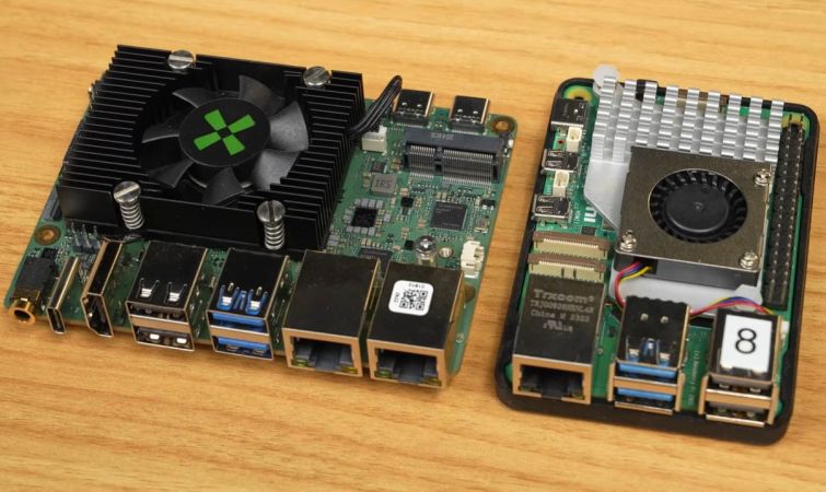
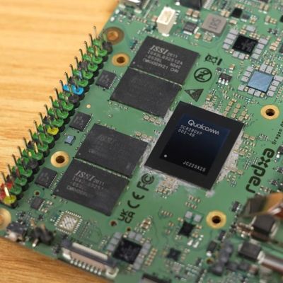
Although the asking price of $209 plus shipping seems high for the Radxa Dragon Q8B, featuring the Qualcomm SC8280XP and 8 GB of LPDDR4X, this is 2026, and amid the RAMpocalypse, even the 8 GB LPDDR4X-equipped Raspberry Pi 5 now costs $175. This, to [Jeff Geerling], makes it fair to directly compare the two to see whether you may want to consider this board for more intense computing purposes.

There’s also a written summary of the results and details in a GitHub issue, though the direct comparison with the Raspberry Pi 5 is in the video.

Although this Qualcomm SoC isn’t new, its primary use is for Windows laptops, which gives somewhat of a hint as to what its performance may be like, tempered by the fact that it was announced in 2021.

The Dragon QXB offers about 2x everything over the RPi5, plus Windows and UEFI support. For Linux, it appears that you still need customized images, which seems perplexing in light of the UEFI aspect. You also have to pick between different Linux images from Radxa and use their Rsetup update tool, making it a less than newbie-friendly offering.

Continue reading “Poking At The Radxa Dragon Q8B Raspberry Pi 5 Killer” →

Getting To Know The TP223 Capacitive Touch Sensor

Mechanical and prone to failure, switches can seem quaint these days. Plus, everyone is used to having touch screens on their phones and other devices. So why not use touch sensors on your next project? [Tarantula3] has details on using the TP223 instead of ordinary switches.

These inexpensive modules work through plastic, glass, or wood, opening up many interesting possibilities for building a front panel. Of course, the thicker the surface above the module, the less sensitive the switch is, but that’s not always a bad thing. In particular, you may want to reduce sensitivity anyway. Thicker panels, reducing the size of the touch pad, or adding an external capacitor can reduce the sensor’s range.

You may be worried about eating up batteries with a bunch of electronic switches. But according to [Tarantula3], the modules consume less than 2 microamps at rest. You can configure the modules with our favorite scripting language: solder. There are two jumpers, initially unsoldered, and this results in four possible states. By default, the output goes high when someone is touching the sensor and stays high until they release.

However, you can solder jumper A to invert the output. Jumper B causes the switch output to toggle on each press. Of course, you can also do both jumpers, which toggles but has the opposite default state. If you get false triggers, consider adding a small capacitor to filter the power supply to the module.

These would be great “drop ins” for 3D printing to add switches to your designs. You might even be able to use these as power switches with a little work.

Ways To Empirically Identify A Magnet’s Polarity

Every magnet has a north and a south pole, but which is which? Sometimes it matters. If a product one builds features a magnetic closure or other part, the polarity of those magnets should be consistent in assembly. So how does one ensure they never glue a magnet wrong again? [Clough42] shows several ways to identify a magnet’s north and south poles using things many of us probably have ready at hand, and goes into a bit of theory while he’s at it.

Probably the easiest way is to use a known-good and clearly labeled reference magnet. Same poles repel, and opposites attract. But if that’s not available, a simple magnetic compass can help. Because opposite poles attract, a compass’s north point will be attracted toward a magnet’s south pole, and vice versa.

A Hall effect sensor, or an electromagnet — the winding and current flow determine the polarity — are other ways to measure a magnet’s poles. And here’s where [Clough42] dives into some details of how magnetic fields actually act, because it explains some seemingly strange behavior.

For example, at around 4:08 he demonstrates a Hall effect sensor board that is documented as lighting an LED when the south pole of a magnet is held to its front. It does that, but it also lights the LED when the north end of the magnet is held to the sensor’s back. That’s because the sensor isn’t actually directly sensing the magnet’s pole, it’s sensing the orientation of a magnetic field. The lesson is clear: make sure you’re measuring what you think you’re measuring. Near the end of the video he demonstrates a similar experience with a handy mobile phone app that senses magnetic fields by reading the device’s internal magnetic compass; by waving a strong magnet around, the detected polarity flips back and forth even though the magnet’s orientation isn’t changed.

So what does one do after positively identifying a magnet’s north and south poles? Label it clearly for use as a known-good reference magnet in the future is our suggestion. Watch the whole video below, then take a few minutes to dive into the nitty-gritty of what magnets actually are and how they work.

Continue reading “Ways To Empirically Identify A Magnet’s Polarity” →

The Different Ways To Look At Negative Resistance

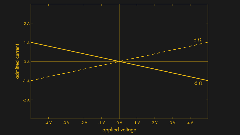
[lcamtuf] has an in-depth look at the concept of negative resistance that goes somewhat further than one might expect. Normally, as voltage across a resistance increases so too does the current. Negative resistance is the concept of current decreasing as voltage increases. But beyond the raw concept, there are a few other ways to look at this idea.

The usual way to think about it is negative differential resistance (NDR). Not everything has a linear relationship between voltage and current, and for a device to exhibit NDR means that in certain ranges the I–V curve actually slopes downward; increasing one of voltage or current decreases the other. This kind of thing occurs in neon lamps. Once they are glowing, increasing current can result in decreasing voltage.

True negative resistance, that of a literal -100 Ω resistor, does not exist. Not in the sense of a passive component, anyway. Such a device would supply power into a circuit rather than dissipating it, and would therefore require an external power source to do so. If that’s not a deal breaker, then it’s actually fairly simple to build one. [lcamtuf] provides a design for a device that uses an op-amp to exhibit ideal constant negative resistance. Naturally it only does so within its operating range; going beyond risks letting out the magic smoke.

Is making a literal negative resistor of practical use? Perhaps only in very specialized situations. But it is worth having a basic understanding if for no other reason than it rears its head in unusual places: the strange tunnel diode comes to mind.

Casting Engine Parts From 3D Prints

After building a couple of internal combustion engines by milling billet aluminium stock and cringing at the absolute waste of material this created, [Camden Bowen] figured he’d give casting metal parts a shot. Of course, the key here is to create the molds for said casting, which is where you got a few options available.

Since DIY is really his thing, he also made his own kiln using cement and perlite, plus a propane burner. For the aluminium material to melt, he bought a stack of aluminium alloy wheels, as these are made of an alloy that’s actually suitable for casting. These were turned into ingots as a first step towards casting the engine parts, which among other things helps to purify the metal.

For the actual casting method he picked lost PLA, meaning the intended shape is 3D printed in PLA, then put into plaster before it’s melted out of the newly minted mold in an oven and subsequently burned out in the kiln. For the plaster [Camden] used regular Plaster of Paris, mixed with sand to give it suitable heat-resistant properties.

After some trial and error, as well as a lot of trouble burning out all the PLA, he got a usable mold and managed to eventually cast an engine cylinder with only a few imperfections. Considering just how convoluted it would have been to mill that part out of billet aluminium, it’s easy to see why commercial manufacturers are casting such parts as well.

Continue reading “Casting Engine Parts From 3D Prints” →